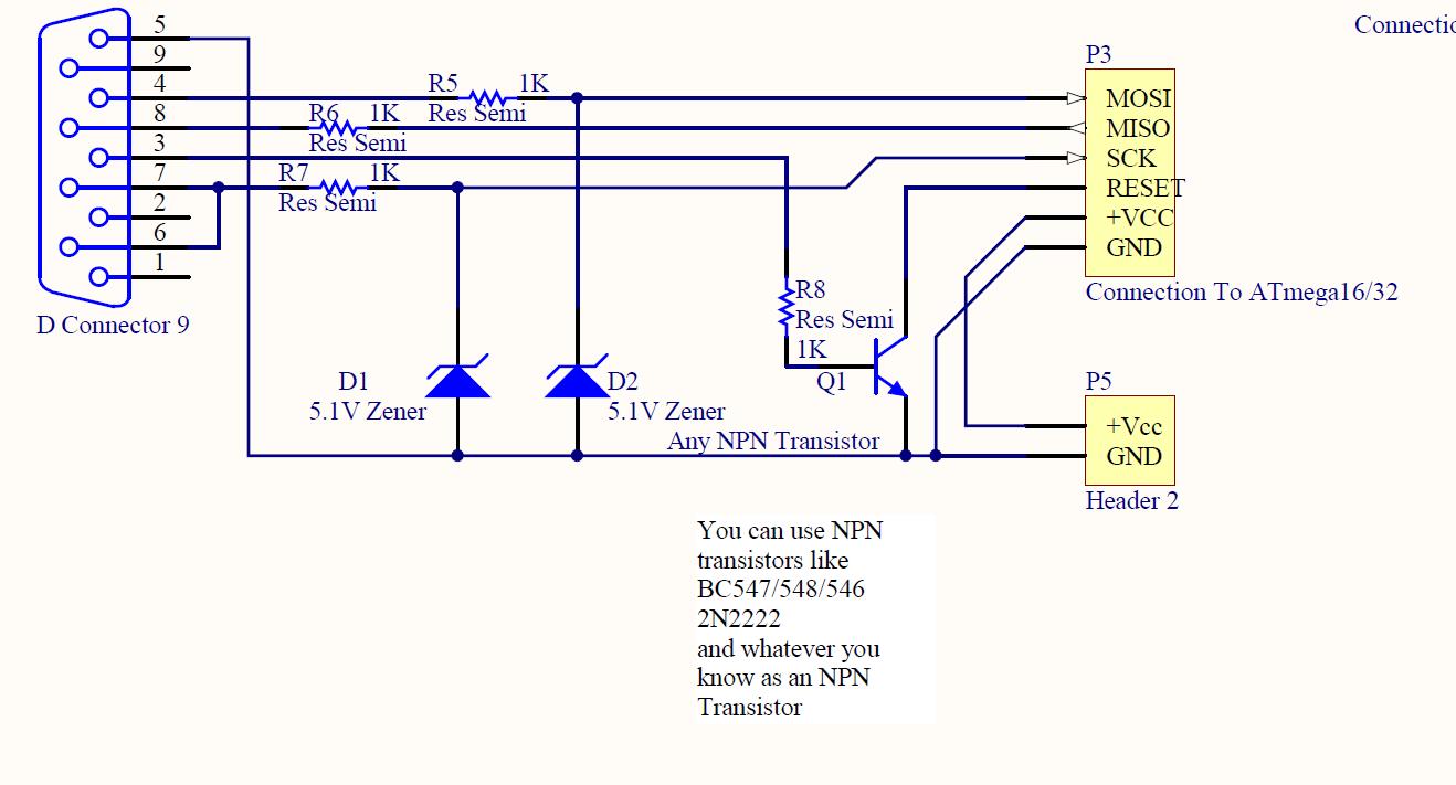

The simplified adapters are not using any semiconductor part, port signals are tied to target device directly as shown in the circuit diagrams. This ISP adapter is designed to reduce cost and to be easy to build. The parallel programmer is controled with AVRPP.EXE(Win32). In this case, a TTL-CMOS level converter, such as 74HC T541, must be put to the place indicated with a dashed line. High level output voltage on the LPT port may not reach 3.5 volts on some PCs. SOIC, TQFP, PLCC are also require socket converter for each package. This programmer is using a 20 pin ZIF socket for device mounting, so that it requires any socket converter when program not 20 pin devices (8,28,40). However 8 pin devices will often require HVS programming mode in order to configure the reset pin as an I/O port. Therefore the parallel programmer is not that required for most case, only an ISP adapter will do.

Programming tiny10/11/28 which has no ISP capability.This programming method is required when the following case. Circuit diagram of this programmer is very simple but it supports both high voltage programming modes Parallel mode and HVS mode. Right image shows built paralell programmer, it is built compact by using many surface mount devices. For details on the each programming mode, please refer to the device data sheets. This programming mode is equivalent to the Paralell Mode and available in only 8/14 pin devices.
#ATMEGA128 SOFTWARE UART SERIAL#
But most AVR programmers use this programming mode even if it has a socket, they have the same problem.Īdditionally, there is serial programming mode using +12V programming voltage that called High-Voltage Serial Programming Mode. Such devices must be programmed in Parallel Mode. However, the ISP mode cannot change fuse bits at some devces, and some devices don't have ISP feature.

This mode requires only three signal lines without +12 volts programming voltage, so that it can also program in the terget system, this is called ISP (In-System Programming). However, most programmers except STK500 seem not to support this programming mode.Īt the ISP Mode, the device communicates via its SPI interface to program and verify. This programming mode is used to pre-program many devices or/and ISP mode cannot use due to the board design. Communicating between the programmer and the device is done in parallel programming commands, so that the programing speed is two times faster than ISP mode. Is it realystic? Do you know of a good tutorial / starting point?AVR has two different programming modes called Parallel Programming Mode (Parallel Mode) and Serial Downloading Mode (ISP mode).Īt the Parallel Mode, the device to be programmed is put on the programmer's socket and +12 volts programming voltage is required to its RESET pin. So I need some help / link on programming the LCP11U24 directly I think (without mbed.h). There is already a project about this but it is, I think, under construction.Īfter googleing, I found an interessting piece of software : I would like to implement a Software UART for mbed (lpc11u24) because there is only one UART. Now I have to implemente a few functions by myself (as written in the code) Internal_tx_buffer = (user_tx_buffer<<1) | 0x200 Static char flag_rx_waiting_for_stop_bit Writes a character to the serial port. Reads a character from the input buffer, waiting if necessary. Tests whether an input character has been received. Clears the contents of the input buffer. Sets the timer to 3 times the baud rate. Background functions to execute while waiting for input. Sets the transmit pin to the low state. Sets the transmit pin to the high state. Returns 0 or 1 dependent on whether the receive pin is high or low. The function init_uart() must be called before any comms can take place The baud rate can be configured by changing the BAUD_RATE macro as

Colin Gittins, Software Engineer, Halliburton Energy Services * There is a facility for background processing while waiting for input * putchar(), getchar(), kbhit() and flush_input_buffer() are available the baud rate, and two software read/write pins for the receive and Generic software uart written in C, requiring a timer set to 3 times


 0 kommentar(er)
